import os
from qiskit import QuantumCircuit, transpile
from iqm.qiskit_iqm import IQMProviderExample: Using QX to Submit Jobs
This guide demonstrates how to submit quantum circuits to devices on QX. For detailed API documentation and additional resources, please refer to the IQM documentation.
Step 1: Installing Python library dependencies
This notebook requires a Python virtual environment with following libraries installed.
For specific client library versions, please refer to the device documentation:
The following packages listed below could be saved as requirements.txt:
iqm-client[qiskit,cirq]>=34.0.0,<=35.0.0
matplotlib
pylatexenc
# For pulse level access
iqm-pulla>=13.0.0,<=14.0.0First, create a virtual Python environment with
conda create -n vttqx python=3.11 pip
conda activate vttqx
Then install the dependencies:
pip install "iqm-client[qiskit,cirq]>=34.0.0,<=35.0.0" "iqm-pulla>=13.0.0,<=14.0.0" matplotlib pylatexencIf you prefer using uv for faster installs and reproducible builds:
# Initialize a new project
uv init

# This creates a pyproject.toml file for project configuration
# Then installs dependencies, which will be recorded
uv add "iqm-client[qiskit,cirq]>=34.0.0,<=35.0.0" "iqm-pulla>=13.0.0,<=14.0.0" matplotlib pylatexencOr install from existing requirements:
uv pip install -r requirements.txtStarting Jupyter Notebook
Install Jupyter in your conda environment:
conda activate vttqx
pip install notebook

# Start Jupyter Notebook
jupyter notebook
Install and run Jupyter in your uv-managed environment:
# First, activate your uv environment
source vttqx/bin/activate  # On Windows: vttqx\Scripts\activate

# Install Jupyter
uv pip install notebook

# Start Jupyter Notebook
jupyter notebook
Then we can import the IQM client library and the qiskit Python objects to define a quantum circuit
Step 2: Define your quantum circuit
Next, we define a quantum circuit that prepares a so called Bell state. In the first line we instantiate a QuantumCircuit object, that allocates two qubits. Further more, we give it the name Bell pair circuit.
circuit = QuantumCircuit(2, name="Bell pair circuit")
circuit.h(0)  # Apply a Hadamard gate to the first qubit
circuit.cx(
    0, 1
)  # Apply a CNOT gate withfirst qubit as control qubit and second as target qubit
circuit.measure_all()  # Finally, we add a measurement operation measuring all qubits
circuit.draw(output="mpl")
Step 3. How to submit to VTT QX?
To submit to VTT QX, instantiate the IQMProvider using the base URL and the quantum_computer parameter. The token can be passed directly or set via the IQM_TOKEN environment variable.
provider = IQMProvider(
    url="https://qx.vtt.fi",
    quantum_computer='q50',  # Replace with 'q5' or 'demo' as needed
    token="YOUR_API_TOKEN_HERE"
)
This unified approach works for all VTT QX devices (Q5, Q50, and Demo).
Generate project token
The provider allows us to generate a qiskit Backend object, that describes the quantum architecture that we are targeting. Knowing the details of the target quantum architecture is important for transpilation of our quantum circuits to the native gates and topology of the target device.
To instantiate the backend, the provider will make a call to the server_url, requesting information about the backend. VTT QX requires, that this call is authenticated. A user authenticates itself to VTT QX, by attaching a project token to each request. The project token can be copied from the dashboard in VTT QX.
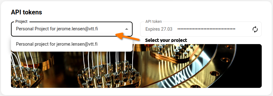
Select the project as shown in the picture above. Next, navigate to the API tokens section and copy the token:
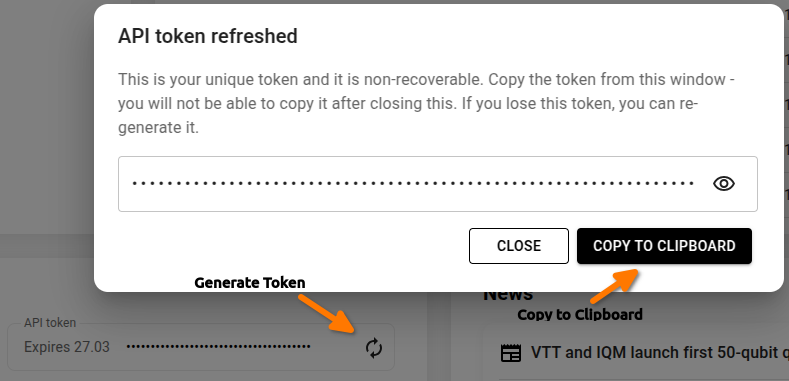
Note: If you don’t see any tokens listed in the API tokens section, you can generate a new token by clicking the refresh button (↻) in the API tokens area. This will create your first API token for the project.
Alternatively, you can generate a new project token by authenticating with an existing active project token. This method is useful when you already have access to a project and want to rotate or generate additional tokens. You can do this by using the following curl command:
curl 'https://qx.vtt.fi/api/projects/{project_id}/token' \
  -X POST \
  -H 'Authorization: Bearer <active_project_token>' \
  -H 'Accept: application/json' \
  -H 'Content-Type: application/json'
Finally, paste the token into the cell below. The token is exposed to the IQM client via the environment variable IQM_TOKEN.
# Set the VTT QX token
os.environ["IQM_TOKEN"] = "<token-here>"

# Note, the token can also be passed directly to the provider without setting IQM_TOKEN:
provider = IQMProvider(
    url="https://qx.vtt.fi", quantum_computer="<device_name>", token="<token-here>"
)
Now, we can generate a backend object, which allows us to print more information about our target device
backend = provider.get_backend()

print(f"Native operations: {backend.operation_names}")
print(f"Number of qubits: {backend.num_qubits}")
print(f"Coupling map: {backend.coupling_map}")
Before executing the circuit, we need to make sure that it only consists of native gates supported by the device
transpiled_circuit = transpile(circuit, backend)Finally, we can also submit the quantum circuit that we defined at the beginning and print the results
for _ in range(1):
    job = backend.run(transpiled_circuit)
    counts = job.result().get_counts()
    print(counts)
Fetching results for large jobs
For jobs with results larger than 50MB, the system automatically converts raw shots to counts. To retrieve these optimized results, use the IQM client’s get_run_counts() method:
from iqm.iqm_client import IQMClient

# Initialize the IQM client
client = IQMClient(url=server_url, token=os.environ["IQM_TOKEN"])

# Get the job ID from your submitted job
job_id = job.job_id()

# Fetch the counts using the IQM client
counts = client.get_run_counts(job_id)
This approach ensures efficient memory usage and faster data retrieval for large-scale quantum experiments.
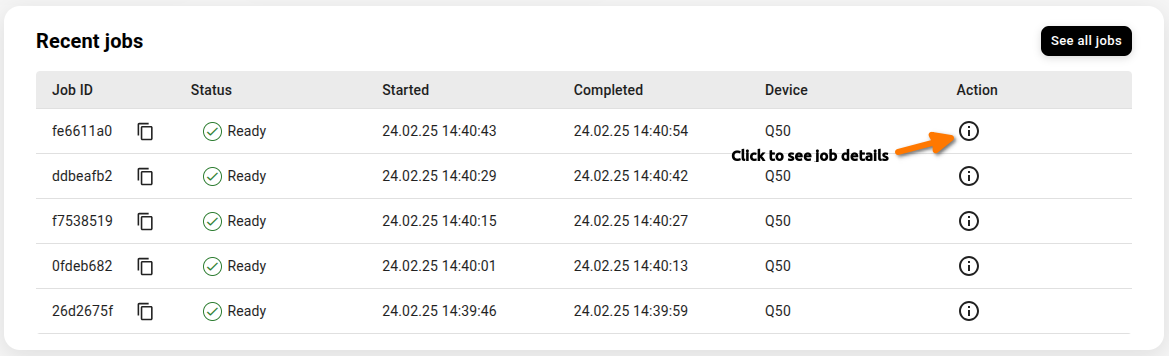
Step 4: Inspecting job results in VTT QX
VTT QX exposes additional information about the job in the UI.
Pulse Level Access
For users who need to submit pulse-level jobs, see the pulse level access example.
Optional: Submitting with Cirq
For Cirq-based circuit submission, see the Introduction to Cirq notebook or the IQM Cirq user guide.
import cirq

q1, q2 = cirq.NamedQubit("Alice"), cirq.NamedQubit("Bob")
circuit = cirq.Circuit()
circuit.append(cirq.X(q1))
circuit.append(cirq.H(q2))
circuit.append(cirq.CNOT(q1, q2))
circuit.append(cirq.measure(q1, q2, key="m"))
print(circuit)
Alice: ───X───@───M('m')───
│ │
Bob: ─────H───X───M────────You can read an OpenQASM 2.0 program from a file (or a string), e.g.
OPENQASM 2.0;
include "qelib1.inc";

qreg q[2];
creg m[2];

x q[0];
h q[1];
cx q[0], q[1];
measure q -> m;
and convert it into a cirq.Circuit object using circuit_from_qasm().
from iqm import cirq_iqm

with open("circuit.qasm", "r") as f:
    qasm_circuit = cirq_iqm.circuit_from_qasm(f.read())
print(qasm_circuit)